FIS-Control MMI/MIB
The FIS-Control MMI/MIB is a monitoring system that can show engine parameters on the multimedia monitor or virtual cockpit of your car in real-time. Additionally it can show notifications of your messenger or email client when an Android phone is connected via Bluetooth. It also offers a CAN bus interface to connect additional sensors.
The FIS-Control MMI supports the following cars
For more information about compatibility and installation click on the specific car.
The FIS-Control MIB supports the following cars
For more information about compatibility and installation click on the specific car.
Contents
About the FIS-Control MMI/MIB
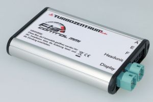
The FIS-Control MMI and FIS-Control MIB units can be placed perfectly invisible behind the headunit in the car. The monitor signal from the headunit, that would normally go directly to the multimedia monitor, is first routed to the FIS-Control. The output of the FIS-Control then goes to the monitor. This way the FIS-Control can either forward the original graphics from the headunit to the monitor, or overlay its own content.
As long as the FIS-Control shows parameters on the screen, it will request that data via the UDS diagnosis protocol from the engine control unit.
It will also monitor the CAN bus for button presses of the multifunction steering wheel as well as the status of the park distance control or rear view camera, in order to automatically switch to the headunit screen again if needed.
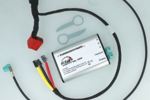
The delivery contents include the FIS-Control box, a specific plug'n'play cable set (exception is the Audi A6/A7/A8) and a removal tool to pull out the headunit.
Installation
The installation may differ between different cars and is described in the specific chapter for each car.
Important: With the current firmware versions the FIS-Control is initially inactive right after the installation. There is no message on the screen. The screen should just show the normal output of the infotainment system. But the FIS-Control will be visible via Bluetooth during the first minute after ignition is switched on (not with Apple iOS). With the FIS-Control updater app it is possible to upload the matching configuration file. Only with a valid configuration the FIS-Control is ready to use.
Features
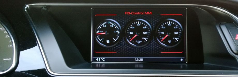
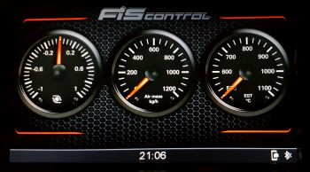
Gauges
The FIS-Control has a gauges view that can show up to three measurement values. The design consists of a background graphic and the graphics for the three needles. The scales and labels of the gauges are part of the background graphic. This allows to fully customize the design and layout of the gauges view. But it also means that it is not possible to change the gauges during run-time without loading new graphics to the FIS-Control.
Additionally it is possible to place up to ten measurement values as numeric gauge. The design is again fully customizable.
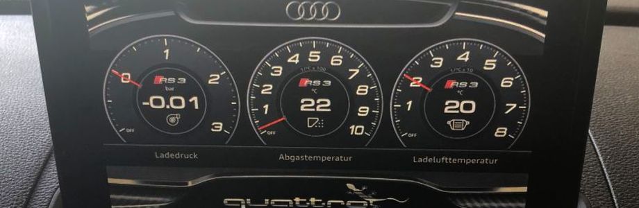
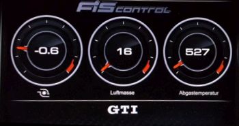
An addition to the gauges view is the Virtual Cockpit view. It shows the parameters as numeric digits in the center of the dials.
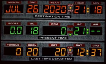
Another layout is based on the time machine of the movie "Back to the Future".
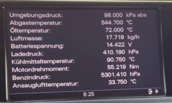
Measurement tables
In the table view the FIS-Control can show between eight and ten measurement values (depending on the capabilities of the engine control unit). In the settings menu you can select one of five tables for this view. So a total of 50 measurement values can be monitored with the FIS-Control. The color of the background and the font can be selected on the configurator web page.
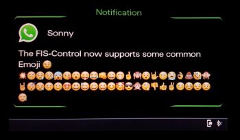
Notifications
There is a notification app for Android available at
https://www.fis-control.de/mmi.html. After the app is installed, you will have to give it "notification access" in the Android settings. As soon as you get into the car and the phone connects the headunit as hands-free device, the notification app will establish a Bluetooth connection to the FIS-Control. The connection will be indicated with a smartphone symbol in the status bar of the FIS-Control. Notifications from WhatsApp, eMail and SMS will now appear on the multimedia monitor. If your email account or messenger is not supported, get in contact with me. Please be aware that the FIS-Control will only show text messages and also only the first few lines of a message. It is not meant to be a fully usable communicator, but just a notification screen.
Operation
The FIS-Control is controlled with three buttons: up, down and set. The assignment of these three buttons depends on the available buttons on the multifunction steering wheel of the car. See the according chapter of the specific car.
With the up and down button you can scroll through three views. The up-most view is the normal headunit view, so the original output of the headunit is shown on the monitor. The second screen is the gauges view of the FIS-Control. The third view is the table view. Dependent on the capabilities of the control unit, the FIS-Control can show a list of up to eight or ten parameters here.
With a long press of the set button you can also toggle between the FIS-Control view and the output of the headunit. If you switched to the headunit view with the set button, you will also have to use the set button to bring up the FIS-Control again. The down button will not work in that case. That is done to allow the use the original function of the up and down buttons without undesired switching of the views on the multimedia monitor.
While you are in the gauges view, a double click to the set button will open the settings menu of the FIS-Control. You can leave it again with a long press to the set key.
While in the table view, a double click on the set button will allow to select one of the five available tables with the up/down buttons. If you confirm with a double click or just wait for 30 seconds, the currently shown table will be selected for the table view.
If the rear view camera or the park distance control is activated, the FIS-Control will automatically switch to the normal headunit view and will stay deactivated until the rear view camera and park distance control get inactive.
If an Android phone with the notification app is connected to the FIS-Control, new notifications will show up automatically. Do a long press to the set key to confirm the notification, or confirm the notification on the phone.
Firmware update
The latest firmware is available at
https://www.fis-control.de/mmi.html. There is also a change log that will list the functional changes.
Most firmware updates will just add support for new engine control units. This is not mentioned in the change log. Every firmware is a complete firmware, so there is no problem to skip updates and just install the latest one. Only thing to consider is, that the format of the configuration file may change from one firmware version to another. So it might be necessary to create a new configuration file with the correct configurator page:
To upload a firmware to the FIS-Control, use the Android App. See chapter
"Using the Android app".
Configure the FIS-Control
The FIS-Control MMI/MIB has no built-in user interface to change the configuration. Instead the following configurator page
https://www.fis-control.de/mmi.html has to be used.
The page allows to load existing configuration files and stores configuration files with the default file name "fis-control.dat". The page just needs a modern web browser like Chrome, Firefox or Edge. So the configuration can be done on a PC (recommended) or also on a smartphone or tablet.
To upload a configuration file to the FIS-Control, use the Android App. See chapter
"Using the Android app".
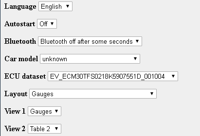
The general configuration items are:
- Language The language of the user interface of the FIS-Control.
- Autostart Selects if either the FIS-Control is automatically shown after ignition start (autostart "On") or the original headunit (autostart "Off"). Additionally a needle sweep can be activated, so that the needles of the gauges go to full scale for a moment. You can select some delay times, because the monitor needs some time after startup before it shows something.
- Bluetooth If the Bluetooth connection is only used to load updates to the FIS-Control, the FIS-Control can power off its Bluetooth module about 60 seconds after ignition start ("Bluetooth off after some seconds"). If you want to show notifications from your smartphone on the multimedia screen, keep the "Bluetooth permanently on".
- Car model As the CAN bus messages between the car models differ, the FIS-Control has to know in which car it is installed.
- Layout "Gauges" shows up to three dials with an optional indicator dot that indicates the maximum value of the last 10 seconds. "Virtual Cockpit" is similar, but additionally shows the current value as numeric digits in the center of the corresponding dial. "Back to the Future Temporal Display Unit" shows the parameters as LED digits. "Gradient circle" is like the "Virtual Cockpit" view, but add colored rings to the scales
- Table View Select one of the five tables that shall be shown on the second screen of the FIS-Control by default.
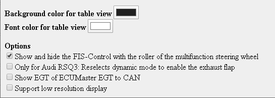
- Background color for table view Should be self-explaining.
- Font color for table view Should be self-explaining.
Configure the parameters
Before you start to fill the tables with parameters, you first have to select the
ECU dataset that fits to your engine control unit. You can read out the dataset version with diagnostic tools like VCDS and OBDeleven even before you install the FIS-Control. Or you can read that information with the FIS-Control using the Android app. See chapter
"Using the Android app".
If the dataset of your car is not yet available in the selection list on the configuration page, get in contact with me and I will add it.
After the correct dataset was selected, the configurator page may need some time to get responsive again. This is because there is some processing done in the background to fill the parameter lists of the tables.
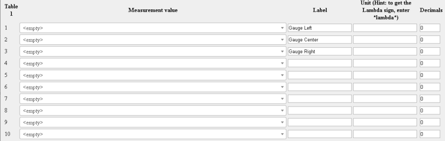
Now you can fill the
tables with the
measurement values that you want to monitor with the FIS-Control. Click on the selection list of each row. There is a search box at the top of the selection list, where you can enter a key word for the value that you are looking for (e.g. "oil" or "pressure") or just scroll through the list and pick the wanted value. Depending on your control unit, you will be able to monitor a maximum of eight or ten values per table. If your control unit can only output eight values simultaneously, leave two of the ten entries "<empty>". If you selected more measurements than your control unit can handle, the FIS-Control will not show any measurement values at all. In that case decrease the number of used parameters per table.
Table 1 has a special meaning, as it is also used to configure the parameters for the three gauges of the gauges view. Row 1 of the Table 1 is for the left gauge, row 2 for the center gauge and row 3 is for the right gauge. For the "Back to the Future" view, the table 1 specifies the parameters that are shown in the second and third row of the "time machine". The first row is automatically filled with the current date (does not work in all cars) and time.
For every parameter you can give a
Label that is shown on the table view of the FIS-Control (but not on the gauges view. The labels of the gauges view have to be part of the background graphic). And you can also enter the unit of a measurement value. Please make sure, that the given unit corresponds to the actual unit that is indicated in brackets in the parameter list. The FIS-Control will not convert the units. For example if the value has the unit "hPa" (hectopascal) you can label the unit "mbar" (millibar) as well, because 1 hPa is 1 mbar. But you should not label the unit "bar".
The column
Decimals is used for the "Virtual Cockpit" and "Back to the Future" view of the FIS-Control. There it will specify how many digits after the decimal point will be shown.
The column
Factor allows to convert the reading of a parameter to other units, for example PSI, Fahrenheit or AFR.
The column
Boost pressure allows to show the boost pressure as gauge pressure instead of absolute pressure. This is done by subtracting the current ambient pressure from the absolute pressure reading. To make this work, you have to have the parameters for absolute pressure and ambient air pressure on the same table. Also you have to indicate, which row in the table is which pressure. If the control unit outputs the two parameters with different units, you have to convert the unit for the ambient pressure to match the unit of the absolute pressure that comes from the control unit.
With the columns
Lower warning and
Upper warning you can define thresholds. If the current measurement value exceeds the Lower warning or Upper warning, the value will be highlighted in red in the table view and in the Virtual Cockpit view.
Options
- Show and hide the FIS-Control with the roller of the multifunction steering wheel The FIS-Control can be opened with the roller or the up/down buttons of the multifunction steering wheel.
- Only for Audi RSQ3: Reselects dynamic mode to enable the exhaust flap This may only work in the Audi RSQ3. When the ignition is started, the FIS-Control will read the current state of the "Drive Select". If it is in "Dynamic", it will cycle through all modes until it is at "Dynamic" again. This will enable the exhaust flap right after ignition.
- Show EGT of ECUMaster EGT to CAN This will show the Exhaust gas temperature of a ECUMaster EGT-to-CAN box in the lower left of the gauges view, when that box is connected together with the FIS-Control to the diagnosis-CAN.
- Support low resolution display This will change the font for the table view and the notifications, so that the FIS-Control can be used with monitor that have lower resolution.
- Ignore rearview camera and park distance control If you do not want, that the FIS-Control automatically switches to the rearview camera or PDC screen, then enable this option.
- Scroll through all tables Instead of one table view, the FIS-Control will show all configured table views, wihtout the need to switch to the selection mode.
- Hide status bar in gauge view The status bar with the clock and the Bluetooth state is not shown for the gauges view.
- Hide status bar in table view The status bar with the clock and the Bluetooth state is not shown for the table view.
- Layout for Virtual Cockpit If the FIS-Control is shown in the Virtual Cockpit of the RS3 or TTRS, the table views are aligned to the shape of the instrument cluster.
- For A3 8V and TT 8S: Use star button This allows the one button operation of the FIS-Control with only the Star button of the multifunction steering wheel. With this option the roller of the steering wheel is ignored. A quick double click shows and hides the FIS-Control, a normal click browses through the views.
- Use texture as background for table view In addition to the background graphic for the gauges view, it is possible to load a texture with 96x96 pixels to the FIS-Control. This texture will be used as background graphic for the table view.
- For A3 8V facelift: Hide FIS-Control when Drive Select button is pressed Will hide the FIS-Control for 3 seconds when the drive select button was pressed.
- For A3 8V facelift: Hide FIS-Control when an MMI button is pressed Will hide the FIS-Control for 3 seconds when an MMI button is used.
- Send warning status to external CAN board A CAN message with ID 0xF15BEEB is sent to the diagnostics CAN when a measurement value reaches its threshold limit.
- For A3/A6/A7/A8: Show FIS-Control when switching gearbox to S Automatically shows the FIS-Control when the gearbox is switched to S.
- Allow to show FIS-Control after a diagnostic session was detected Normally the FIS-Control will disable itself until next ignition cycle when it detects another diagnostic session on the CAN bus, even if the other diagnostic session was stopped. This is to prevent problems in the workshop. This option will allow to call the FIS-Control after the other diagnostic session has ended without switching the ignition off and on.
- For Golf Mk7: Use double click on Start/Stop button to show FIS-Control and longpress to toggle views Some Golf Mk7 don't have a multifunction steering wheel. In order to operate the FIS-Control a long press or double click on the button for the Start/stop system can be used.
- For Audi A3/A4/A5/Q5: Zeitenjagd If you do a run from 0 to 100 kph or 100 to 200 kph, an info screen with the times will be shown.
- For A1 8X: Use navi button This allows the one button operation of the FIS-Control with only the NAV button of the multifunction steering wheel. With this option the roller of the steering wheel is ignored. A quick double click shows and hides the FIS-Control, a normal click browses through the views.
- For A4/A5/Q5: Show startlogo It is possible to upload a startlogo file. (Currently I have to create that, just send me your template with 800x480 pixels.)
- Shiftlight If the value of the middle gauge reaches its threshold limit, the gradient circle starts to blink.
Customize the gauges
The main view of the FIS-Control is the gauges view. The design for the gauges is fully customizable and consists of a background graphic and three needle graphics. There is a design template for the gauges available. This template is also preinstalled to the FIS-Control. But this template does not include the scales and labels for the measurements. So at least you should add the correct scale to the background graphics. I use the free shareware tool PhotoLine for this (
https://www.pl32.com).
The template is available at
https://www.fis-control.de/mmi.html. After you modified the background graphics, save it as PNG image. Make sure, that the pixel resolution is 800x480. Even if your car has a monitor with the lower resolution (400x240), the image file has to have the full resolution, but you will only see the upper left quarter of the image on your monitor. Before you can upload own background and needle graphics, they have to be converted to a binary file format. This can be done with the graphics converter web page:
https://www.fis-control.de/graphics-converter.html
The maximum size of a needle is 8192 pixels. So it can be for example 90x90 pixels or 128x64 and of course everything smaller. The needle images should have a transparent background. So make sure you save your self created images as PNG with alpha channel.
Here is a tutorial video on how to modify the gauges:
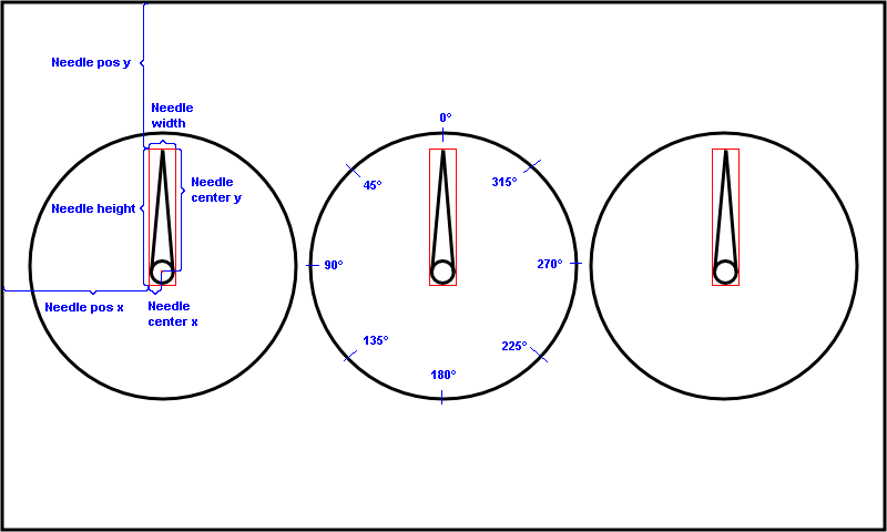
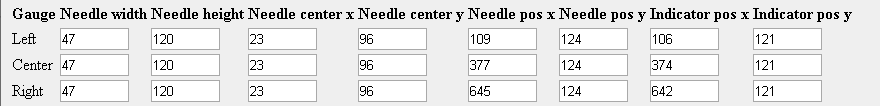
If you change the position of the gauges or the needle dimensions, you have to also change the configuration file of the FIS-Control accordingly. Enter the pixel width (Needle width) and height (Needle height) of your needle images and the position of the rotation point (Needle center x, Needle center y). Depending on your needle design, it is allowed to have the rotation point outside of the needle graphic. Also set the pixel position (Needle pos x, Needle pos y) of the upper left corner of your needle image, when it is in 12 o'clock position, relative to the upper left corner of the background graphic.
The indicator (Indicator pos x, Indicator pos y) is a small red dot that will show the maximum needle position of the last 10 seconds. As a rule of thumb, set the indicator position to the same as the needle minus 3. If you don't want to have the indicator dots, set the positions to 0.
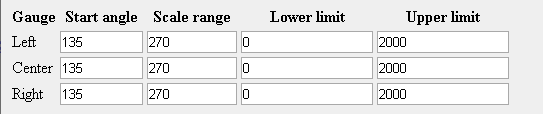
Every gauge has a Lower limit and an Upper limit. This is the value range of your gauge. For example if you want a boost gauge that shows pressures between -1 and 2.5 bar, you will have to enter -1 as lower limit and 2.5 as upper limit. Make sure that the values match the unit that is read from the control unit. If the boost pressure is read in mbar, you have to enter -1000 and 2500 instead.
The Scale range is the angle in degrees that the needle will travel between lower limit and upper limit, 270 degrees are 3/4 of a full circle. Another settings that can be configured is the Start angle, that is the needle angle at the lower limit position. As shown above, 0 degrees is the 12 o'clock position. The angle is counted counterclockwise.
Here are some pictures from different designs: Topic: Fotos vom FIS-Control MMI in Aktion
Customize the numerical gauges
In addition to the round gauges it is possible to include numerical gauges of all measurement values of the first table to the FIS-Control.
The font for the numerical gauges is user defined. For every digit between 0 and 9 and also for the minus sign and the decimal point, a separate grayscale graphic has to be created. Together with the needle graphics they can be combined to a .bin file with the graphics converter.
Please make sure that all digits have the same pixel height. The numbers and the minus sign also have to have the same width. These dimensions have to be entered into the configurator in the
Numeric gauge section.
The grayscale defines the opacity of the numbers. White means transparent, black means opaque. The graphics do not define the color on which the numbers will be shown later on. The color is set in the configurator.
You also have to tell the configurator, where to place the numerical gauges on the screen. The coordinates set the right upper bound of the position. If you do not want to show a measurement as numerical gauge, just keep both coordinates (x and y) at 0.
In the settings for table 1 you can also specify in the column
Decimals how many digits after the decimal point shall be shown for that parameter.
Here is a tutorial video on how to create the numerical gauges:
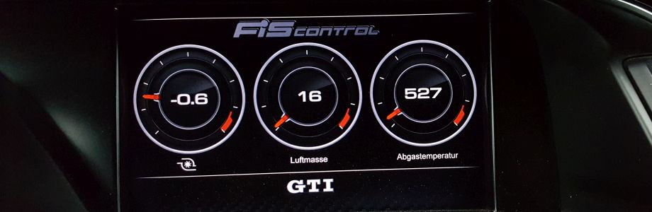
Customize the gradient circles
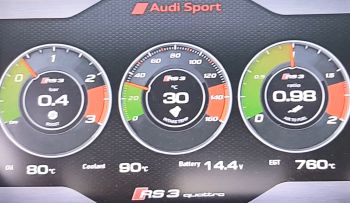
The layout "Gradient circle" allows to configure colored rings for all three round gauges. For every gradient circle you have to define an "outer radius" and "inner radius". The unit of the radius is pixels. The maximum radius is 199 pixels.
The color gradient itself is specified in the section "Color range". You can give up to 10 color areas for each ring. Let's say you have a gauge for RPM between 0 and 8000 RPM and you want to have a green range from 0 to 6000 RPM, then a yellow range that fades to red up to 7000 RPM and a red range over 7000 RPM, settings could look like this:
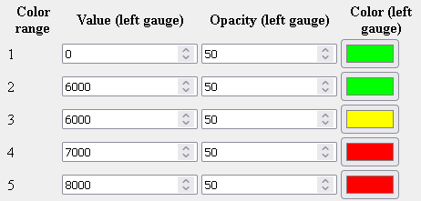
The opacity can be set in percent. If color or opacity is not identical for the end of a range and the start of the next range, the FIS-Control will automatically fade from start to end color/opacity.
Using the Android app
The Android app is available at
https://www.fis-control.de/mmi.html. In order to install the app you have to allow to install apps from external sources. If a previous version is already installed, remove it first.
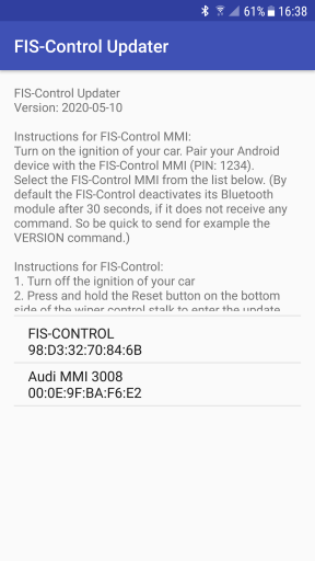
After the ignition is switched on, the FIS-Control will enable its Bluetooth module for about 60 seconds or permanently, depending on its configuration. You have to pair the FIS-Control to your phone in the Android Bluetooth settings menu. The PIN is 1234.
After the FIS-Control is paired, you can launch the app and pick the FIS-CONTROL in the device list. If that fails, you may have exceeded the 30 seconds. In that case just restart the ignition. After a restart of the ignition, you will also have to reselect the FIS-Control in the app, either by restarting the app or by clicking the back button to get back to the device selection list. Be quick and send a command to the FIS-Control, for example by selecting "Firmware version" from the drop down list and hitting SEND. After the first received command, the FIS-Control will keep the Bluetooth module enabled. If the connection still fails and you are also using the FIS-Control notification app, open the notification app and click "STOP SERVICE" before you turn on the ignition.
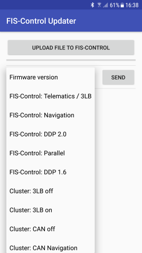
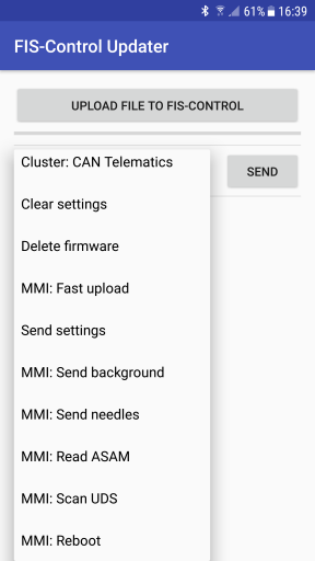
The drop down list of the FIS-Control app will list some commands, that are only needed for other versions of the FIS-Control. For the FIS-Control MMI/MIB the following commands are valid:
- Firmware version This will show the build date of the currently installed firmware.
- Delete firmware This will delete the current firmware from the FIS-Control. After next ignition start, the FIS-Control will wait for a new firmware via Bluetooth.. and nothing else. This can also be used to deactivate all of the FIS-Control functions for testing purposes.
To upload a new firmware, cycle the ignition and restart the app. You should now see the letter "C" arrive once per second in the text window of the app. This means that the FIS-Control is ready to receive a file. Click "UPLOAD FILE TO FIS-CONTROL" and select the firmware file. You should see the message "File upload started". And after some minutes the message "File upload complete". The progress bar should move slowly during the upload process. After the upload is finished, wait at least 5 seconds. Now you can turn off the ignition. After next start of the ignition, the new firmware will get active.
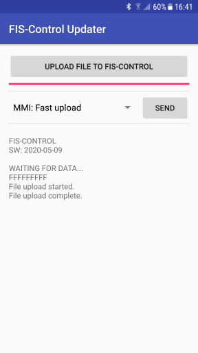
- MMI: Fast upload This can be used to upload firmware updates, background graphics, needle graphics and configuration files to the FIS-Control. The "fast upload" is a about ten times faster than the other upload methods, but it has no retry mechanism in case the Bluetooth connect is disturbed. So the "fast upload" may fail or get stuck. In that case, try again or use the slower upload methods. Please follow the instructions on the headunit screen. Also check for the message "Checksum ok" to be sure that the file transfer was successful. Do not turn off the ignition before you see that "Flashing the file" is "Complete" or the headunit screen in shown again. Don't trust the output in the app, because this only tells that the file transfer to the FIS-Control is complete, but not the writing to the flash memory of the FIS-Control.
- Send settings Send this command and then click on "UPLOAD FILE TO FIS-CONTROL" to send a configuration file to the FIS-Control. You should see the message "File upload started". And after some seconds the message "File upload complete". The progress bar should move slowly during the upload process. The new settings will get effective next time you turn on the ignition or after you send the command "MMI: Reboot".
- MMI: Send background Send this command and then click on "UPLOAD FILE TO FIS-CONTROL" to send a background graphic to the FIS-Control. You should see the message "File upload started". And after some minutes the message "File upload complete". The progress bar should move slowly during the upload process.
- MMI: Send needles Send this command and then click on "UPLOAD FILE TO FIS-CONTROL" to send the needle graphics to the FIS-Control. You should see the message "File upload started". And after some minutes the message "File upload complete". The progress bar should move slowly during the upload process.
- MMI: Read ASAM This can be used to read the ASAM dataset version of the installed engine control unit. This helps to pick the correct dataset on the FIS-Control configurator.
- MMI: Scan UDS This function will perform a scan for all measurement values that are available on your engine control unit. This information will help me to add more measurement values for your car. So if you want to help me with the development of the FIS-Control, please run the "Scan UDS" function and send me the result that is shown in the text windows of the app. You can do a long press to the text field to select the whole text and copy it, so you can paste it into an email. Preconditions: A valid configuration file with the correct ASAM dataset is loaded to the FIS-Control. Ignition on, but engine off. The FIS-Control should not be shown on the multimedia monitor as long as the scan runs (about 3 minutes), so that no other diagnosis communication is ongoing.
- MMI: Reboot This will restart the FIS-Control, just like it would when you cycle the ignition. This is useful after a new configuration file was sent to the FIS-Control and you want to make it active.
FAQ
- Is it also possible to use an iPhone together with the FIS-Control?
No, the Bluetooth profile that is used by the FIS-Control is not supported by iOS.
- Is there a FIS-Control for the Audi A6 4F?
No. From what I saw, the engine control units of the A6 4F are still using the old KWP2000 protocol, that is not supported by the FIS-Control MMI/MIB.
Audi A1 8X (from 05/2010)
Compatibility
The FIS-Control MMI can be used in the A1 8X. Preconditions: The headunit MMI 3G+ or RMC (Low monitor resolution) is installed and the engine control unit supports the UDS diagnostics protocol.
Installation
- Turn off the ignition
- Pull out the headunit with the removal tool, just as far that you can unplug the connectors of the front panel (the grip of the tool might be sharp, don't hurt yourself).
- Unplug all cables at the backside of the headunit.
- Unplug the 20 pin connector of the CAN gateway behind the footwell trim. There is a tap on the connector that has to be pressed to unlock it before pulling.
- Lead the provided cable set from the CAN gateway to the center console. As the cable set has just the needed length, it is easier to first plug the cables to the FIS-Control box and insert the headunit into the center stack before plugging the other end of the cable set to the CAN gateway.
- Plug the provided cable set to the FIS-Control box:
- The plug with the black shrinking hose belongs to socket A
- The plug with the yellow shrinking hose belongs to socket E
- The plug with the red shrinking hose belongs to socket F
- Connect the round 4-pin connector that comes from the monitor to the "Display" socket of the FIS-Control. If the cable has the pink connector, you will have to cut one coding tab to make it fit.
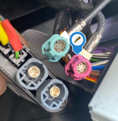
- Connect the provided round 4-pin connector into the gray or pink socket of the headunit and the other end to the "Headunit" socket of the FIS-Control.
- Plug in all cables to the backside of the headunit. Make sure that the cables are routed in a way that allows to slide in the headunit into the center console easily.
Buttons
The FIS-Control can be controlled with the roller and the menu button on the left side of the steering wheel.
Known issues
- The FIS-Control will only pass-through the monitor signal as long as the ignition is on. That means the the display will get black as soon as you turn off the ignition, even if the headunit is still running.
- The buttons of the multifunction steering wheel keep their original function. So a push to a button will not only trigger a function of the FIS-Control, but also its normal function (e.g. changing the view of the trip computer).
Audi A4 8K (from 05/2009 to 08/2015)
Audi A5 8T (from 11/2008 to 06/2016)
Audi Q5 8R (from 11/2008 to 2017)
Compatibility
The FIS-Control MMI can be used. Preconditions: The headunit MMI 3G High or MMI 3G+ is installed and the engine control unit supports the UDS diagnostics protocol. The MMI 3G basic does also work, but the screen resolution is much lower.
Installation
- Turn off the ignition
- Pull out the headunit with the removal tool, just as far that you can unplug the connectors of the front panel (the grip of the tool might be sharp, don't hurt yourself).
- Unplug all cables at the backside of the headunit.
- Remove the glove-box.
- Unplug the 20 pin connector of the CAN gateway. There is a tap on the connector that has to be pressed to unlock it before pulling.
- Insert the provided cable set between the CAN gateway and the original cable harness.
- Lead the provided cable set from the CAN gateway to the center console.
- Plug the provided cable set to the FIS-Control box:
- The plug with the black shrinking hose belongs to socket A
- The plug with the yellow shrinking hose belongs to socket E
- The plug with the red shrinking hose belongs to socket F
- Connect the gray round 4-pin connector that comes from the monitor to the "Display" socket of the FIS-Control.
- Connect the provided round 4-pin connector into the gray socket of the headunit and the other end to the "Headunit" socket of the FIS-Control.
- Plug in all cables to the backside of the headunit. Make sure that the cables are routed in a way that allows to slide in the headunit into the center console easily.
Buttons
The FIS-Control can be controlled with the roller and the MODE button on the left side of the steering wheel.
Known issues
- The FIS-Control will only pass-through the monitor signal as long as the ignition is on. That means the the display will get black as soon as you turn off the ignition, even if the headunit is still running.
- The buttons of the multifunction steering wheel keep their original function. So a push to a button will not only trigger a function of the FIS-Control, but also its normal function (e.g. changing the view of the trip computer).
Audi Q3 8U (from 10/2011)
Audi Q7 4L (from 05/2009 to 03/2015)
Compatibility
The FIS-Control MMI can be used in the Q3 8U and Q7 4L. Preconditions: The headunit MMI 3G+ is installed and the engine control unit supports the UDS diagnostics protocol.
Installation
- Turn off the ignition
- Pull out the headunit with the removal tool, just as far that you can unplug the connectors of the front panel (the grip of the tool might be sharp, don't hurt yourself).
- Unplug all cables at the backside of the headunit.
- Unplug the 20 pin connector of the CAN gateway behind the footwell trim. There is a tap on the connector that has to be pressed to unlock it before pulling.
- Lead the provided cable set from the CAN gateway to the center console. As the cable set has just the needed length, it is easier to first plug the cables to the FIS-Control box and insert the headunit into the center stack before plugging the other end of the cable set to the CAN gateway.
- Plug the provided cable set to the FIS-Control box:
- The plug with the black shrinking hose belongs to socket A
- The plug with the yellow shrinking hose belongs to socket E
- The plug with the red shrinking hose belongs to socket F
- Connect the round 4-pin connector that comes from the monitor to the "Display" socket of the FIS-Control.
- Connect the provided round 4-pin connector into the gray socket of the headunit and the other end to the "Headunit" socket of the FIS-Control.
- Plug in all cables to the backside of the headunit. Make sure that the cables are routed in a way that allows to slide in the headunit into the center console easily.
Buttons
The FIS-Control can be controlled with the roller and the menu button on the left side of the steering wheel.
Known issues
- The FIS-Control will only pass-through the monitor signal as long as the ignition is on. That means the the display will get black as soon as you turn off the ignition, even if the headunit is still running.
- The buttons of the multifunction steering wheel keep their original function. So a push to a button will not only trigger a function of the FIS-Control, but also its normal function (e.g. changing the view of the trip computer).
Audi A3 8V (from 05/2012)
Compatibility
The FIS-Control MIB can be used in the A3 8V. Preconditions: The headunit MIB1 High or MIB2 High is installed and the engine control unit supports the UDS diagnostics protocol. The MIB1 Standard does also work, but the screen resolution is much lower.
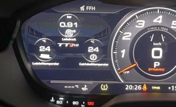
On facelift models with Virtual Cockpit that have a view where the RPM gauge is centered, it is also possible to show the FIS-Control on the cluster instead of the MMI screen.
Installation
- Turn off the ignition
- Pull out the headunit in the glove-box with the removal tool, just as far that you can unplug the connectors on the backside (the grip of the tool might be sharp, don't hurt yourself).
- Unplug all cables at the backside of the headunit.
- Unplug the 20 pin connector of the CAN gateway behind the footwell trim. There is a tap on the connector that has to be pressed to unlock it before pulling.
- Insert the provided cable set between the CAN gateway and the original cable harness.
- Use the provided extension cable to lead the cable from the gateway to the glove-box. Make sure you connect the wires correctly, especially the 4-pin connector of the cable with the yellow shrinking hose (some have plugged the extension cable 90° or 180° twisted, that is wrong).
- Plug the provided cable set to the FIS-Control box:
- The plug with the black shrinking hose belongs to socket A
- The plug with the yellow shrinking hose belongs to socket E
- The plug with the red shrinking hose belongs to socket F
- Connect the round 4-pin connector that comes from the monitor to the "Display" socket of the FIS-Control. You will have to carefully unwrap the original cable harness that leads to the headunit, so that the monitor cable is long enough to lead it to the FIS-Control. If the cable has the pink connector, you will have to cut one coding tab to make it fit.
- Connect the provided round 4-pin connector into the gray or pink socket of the headunit and the other end to the "Headunit" socket of the FIS-Control.
- Plug in all cables to the backside of the headunit. Make sure that the cables are routed in a way that allows to slide in the headunit into the center console easily.
Buttons
The FIS-Control can be controlled with the roller and the menu/view button on the left side of the steering wheel. Or with the star button.
Known issues
- The FIS-Control will only pass-through the monitor signal as long as the ignition is on. That means the the display will get black as soon as you turn off the ignition, even if the headunit is still running.
- The buttons of the multifunction steering wheel keep their original function. So a push to a button will not only trigger a function of the FIS-Control, but also its normal function (e.g. changing the view of the trip computer).
Audi A6 4G (from 04/2011)
Audi A7 4G (from 07/2010)
Audi A8 4H (from 03/2010)
Compatibility
The FIS-Control MIB can be used in the A6/A7/A8. Preconditions: The headunit MMI 3G+, MIB1 High or MIB2 High is installed and the engine control unit supports the UDS diagnostics protocol.
Installation
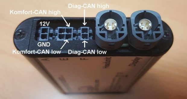
The FIS-Control has to be inserted into the signal path between the headunit and the monitor. The needed HSD cable is included. But there is no plug'n'play cable set available for the CAN buses and power supply. So the included cable set just provides some needed connectors. The wiring has to be done by yourself. You can get the diagnosis CAN and power supply from the back of the OBD socket in your car. The Komfort CAN can be taken from the back of the Climatronic unit. Please note that CAN wires always should be twisted pairs.
Pinout of the OBD socket:
- OBD Pin 1 -> FIS-Control 12V (this is a switched power supply, do not connect the FIS-Control to permanent 12V)
- OBD Pin 4 -> FIS-Control GND
- OBD Pin 6 -> FIS-Control Diag-CAN high
- OBD Pin 14 -> FIS-Control Diag-CAN low
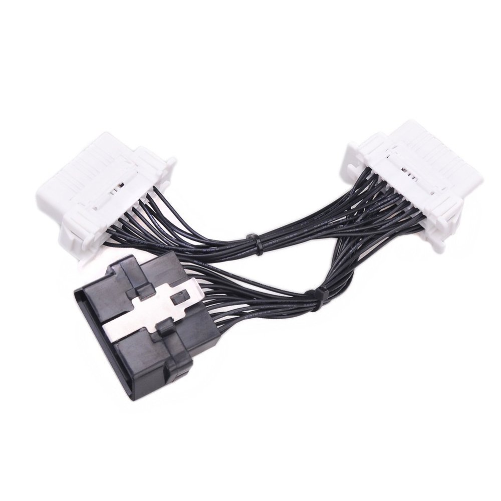
There are Y-cables available, that could make the installation easier:
Pinout of the Climatronic unit (Audi A8):
- T20g/2 (orange/blue) CAN high -> FIS-Control Komfort-CAN high
- T20g/3 (orange/brown) CAN low -> FIS-Control Komfort-CAN low
Pinout of the Climatronic unit (Audi A6):
- T20c/4 (orange/blue) CAN high -> FIS-Control Komfort-CAN high
- T20c/5 (orange/brown) CAN low -> FIS-Control Komfort-CAN low
Buttons
The FIS-Control can be controlled with the roller and the menu button on the left side of the steering wheel.
Known issues
- The FIS-Control will only pass-through the monitor signal as long as the ignition is on. That means the the display will get black as soon as you turn off the ignition, even if the headunit is still running.
- The buttons of the multifunction steering wheel keep their original function. So a push to a button will not only trigger a function of the FIS-Control, but also its normal function (e.g. changing the view of the trip computer).
Audi Q2 GA (from 09/2016)
Audi Q5 (from 2017)
Audi Q7 4M (from 03/2015)
Audi R8 4S (from 05/2015)
Skoda Fabia NJ (from 11/2014)
The FIS-Control is not yet tested in these cars. But it is expected to work. If you want to try, get in contact with me.
Audi TT 8S (from 07/2014)
Compatibility
The FIS-Control MIB can be used in the Audi TT 8S, but only if the Virtual Cockpit offers a view where the RPM gauge is centered.
Installation
Installation is similar to the
Audi A3 8V.
Buttons
The FIS-Control can be controlled with the roller and the menu/view button on the left side of the steering wheel. Or with the star button.
Known issues
- The buttons of the multifunction steering wheel keep their original function. So a push to a button will not only trigger a function of the FIS-Control, but also its normal function (e.g. changing the view of the trip computer).
Seat Leon 5F (from 2013)
Compatibility
The FIS-Control MIB can be used in the Seat Leon 5F. Preconditions: The headunit MIB1 Easy Connect (Low monitor resolution) is installed and the engine control unit supports the UDS diagnostics protocol. Other headunits might be also compatible. Please get in contact with me.
Installation
Installation is similar to the
Audi A3 8V.
Buttons
The FIS-Control can be controlled with the roller and the OK button of the steering wheel.
Known issues
- The FIS-Control will only pass-through the monitor signal as long as the ignition is on. That means the the display will get black as soon as you turn off the ignition, even if the headunit is still running.
- The buttons of the multifunction steering wheel keep their original function. So a push to a button will not only trigger a function of the FIS-Control, but also its normal function (e.g. changing the view of the trip computer).
VW Golf 7
Skoda Octavia A7
Compatibility
The FIS-Control MIB can be used in the VW Golf 7. Preconditions: The headunit MIB1 Discover Media (Low monitor resolution) or MIB2 Discover Media is installed and the engine control unit supports the UDS diagnostics protocol. Other headunits might be also compatible. Please get in contact with me.
Installation
Installation is similar to the
Audi A3 8V.
Buttons
The FIS-Control can be controlled with the up/down buttons and the OK button of the steering wheel.
Known issues
- The FIS-Control will only pass-through the monitor signal as long as the ignition is on. That means the the display will get black as soon as you turn off the ignition, even if the headunit is still running.
- The buttons of the multifunction steering wheel keep their original function. So a push to a button will not only trigger a function of the FIS-Control, but also its normal function (e.g. changing the view of the trip computer).
VW Passat B8
Compatibility
The FIS-Control MIB can be used in the VW Passat B8. Preconditions: The headunit MIB2 Discover Pro is installed and the engine control unit supports the UDS diagnostics protocol. Other headunits might be also compatible. Please get in contact with me.
Installation
Installation is similar to the
Audi A3 8V.
Buttons
The FIS-Control can be controlled with the roller and the OK button of the steering wheel.
Known issues
- The FIS-Control will only pass-through the monitor signal as long as the ignition is on. That means the the display will get black as soon as you turn off the ignition, even if the headunit is still running.
- The buttons of the multifunction steering wheel keep their original function. So a push to a button will not only trigger a function of the FIS-Control, but also its normal function (e.g. changing the view of the trip computer).
VW Polo 6C
Compatibility
The FIS-Control MIB can be used in the VW Polo 6C. Preconditions: The headunit MIB2 Discover Media is installed and the engine control unit supports the UDS diagnostics protocol. Other headunits might be also compatible. Please get in contact with me.
Installation
The FIS-Control has to be inserted into the signal path between the headunit and the monitor. The needed HSD cable is included. But there is no plug'n'play cable set available for the CAN buses and power supply. So the included cable set just provides some needed connectors. The wiring has to be done by yourself. You can get the CAN bus and power supply from the body control unit in your car. Please note that CAN wires always should be twisted pairs.
Pinout of socket C of the body control module:
- T73c/19 - GND
- T73c/42 - CAN-Bus Diagnose High
- T73c/43 - CAN-Bus Diagnose Low
- T73c/46 - CAN-Bus Komfort High
- T73c/47 - CAN-Bus Komfort Low
- T73c/57 - Klemme 15 (12V)
Buttons
The FIS-Control can be controlled with the up/down buttons and the OK button of the steering wheel.
Known issues
- The FIS-Control will only pass-through the monitor signal as long as the ignition is on. That means the the display will get black as soon as you turn off the ignition, even if the headunit is still running.
- The buttons of the multifunction steering wheel keep their original function. So a push to a button will not only trigger a function of the FIS-Control, but also its normal function (e.g. changing the view of the trip computer).